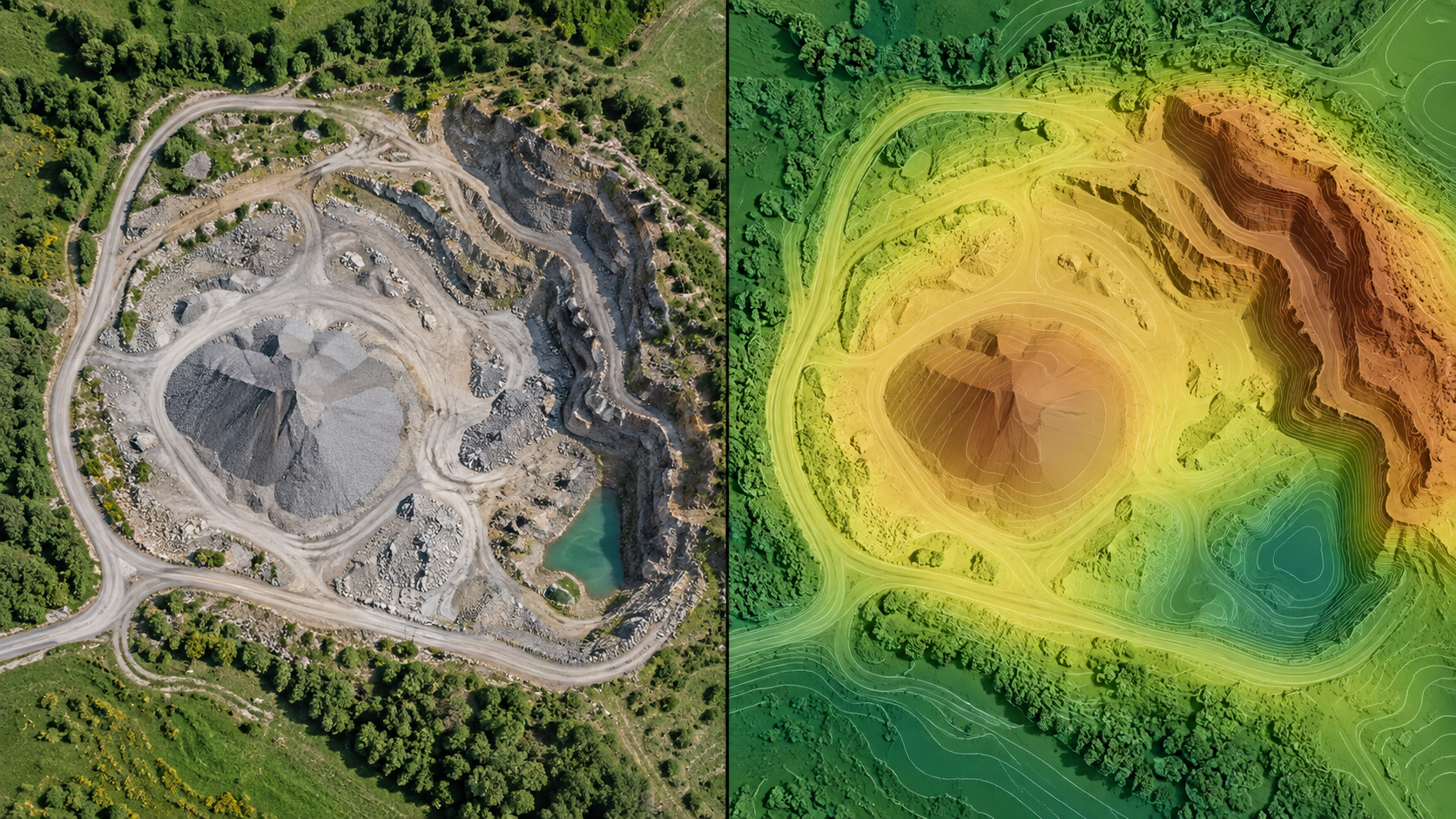
Contours simplify a continuous elevation surface into lines. They can also amplify noise when the interval is too small for the surface quality.
Choose an interval deliberately
Match the interval to terrain relief, intended drawing scale, vertical accuracy, and client specification. A dense line set is not automatically more accurate.
Inspect before export
Review flat-area chatter, spikes, gaps, edge effects, closed depressions, and behavior around buildings or vegetation. Simplification and smoothing must not hide material features.
Preserve spatial metadata
Confirm CRS, units, height reference, layer names, and any origin shift required by the receiving CAD system. Open DXF, GeoPackage, or LandXML in an independent application before delivery.
Include a readme that identifies the source surface revision and contour interval. That small record prevents many downstream interpretation errors.
Choose an interval the surface can support
Contour interval is not a styling choice. It should reflect terrain variation, raster resolution, noise, independent accuracy evidence, and the recipient’s use. A very tight interval on a noisy surface creates busy lines that imply detail the data does not support. Generate a test area first and inspect flat ground, slopes, breaklines, and structures.
Prepare the source surface
Confirm whether contours should come from DSM or DTM. Review classification, nodata, edge artefacts, spikes, pits, water, vegetation, and temporary objects. Apply smoothing only through a documented method and preserve the unsmoothed canonical surface. Do not edit contours into a preferred appearance without recording the change.
Design useful attributes
Store elevation as a numeric field in documented units. Distinguish index contours from intermediate contours, include the project revision and source surface, and retain CRS metadata. Avoid relying on colour or line weight alone because those may disappear in another application.
Test the CAD handoff
Open DXF or other CAD outputs in an independent application, confirm drawing units, coordinates, elevation values, layer names, extents, and text scale. Some CAD workflows interpret geographic coordinates or very large eastings poorly, so agree on a projected CRS before delivery.
Package the contour file with the source-surface description, interval, smoothing method, CRS/vertical reference, units, capture date, limitations, and a checksum.
Example interval test
Contours are requested at 0.1 m because the raster cell size is small. A test area shows jagged closed loops across otherwise flat ground and noisy lines around vegetation. The team reviews checkpoint evidence and surface variation, selects a coarser defensible interval, and documents limited smoothing used only for the delivery derivative.
The DXF is opened in the recipient’s CAD application. Drawing units, layer names, elevation attributes, extents, and insertion position are checked. The canonical raster remains unchanged and accompanies the contour metadata so the lines can be regenerated.
This test avoids two common errors: treating cell spacing as vertical accuracy and assuming a file that exports successfully will be interpreted correctly by downstream CAD software.
Sign-off record
Before relying on the workflow, record the project and revision, source dataset, selected preset or method, coordinate and height references, units, processing version, warnings, exclusions, independent validation, and the artifact used for the decision. Reopen critical outputs in an independent viewer and keep their checksums with the report.
The reviewer should answer four questions in writing: Is the required area supported by source evidence? Does the chosen product actually answer the operational question? Are accuracy and limitations stated without inferring more than the checks prove? Can another person reproduce the result from the retained inputs and settings?
If any answer is no, hold the delivery or label the limitation. A documented stop is safer than a polished output whose assumptions cannot be recovered.